Enrotllament parcial entre la presa central del cable o entre dos cables (quan no hi ha presa central).
Angle de gir del motor sense càrrega, mentre dues fases veïnes estan excitades
La taxa de lamotors pas a pasmoviment de passos continus.
El parell màxim que l'eix pot suportar sense rotació contínua, mentre els cables conductors estan desconnectats.
El parell estàtic màxim que l'eix d'unmotor pas a pasexcitat amb corrent nominal pot suportar sense rotació contínua.
Les velocitats màximes d'impulsos que el motor pas a pas excitat amb una determinada càrrega pot arrencar i sense desincronització.
Les velocitats màximes d'impulsos que pot assolir el motor pas a pas excitat que impulsa una determinada càrrega i que no es desincronitza.
El parell màxim que el motor pas a pas excitat pot arrencar amb una determinada freqüència d'impulsos i sense desincronització.
El parell màxim que un motor pas a pas accionat en condicions prescriptives i una determinada freqüència d'impulsos pot suportar i no es pot desincronitzar.
El rang de freqüència d'impulsos que el motor pas a pas amb càrrega prescriptiva pot arrencar, aturar o revertir, i no mantenir cap desincronització.
El voltatge màxim mesurat a través d'una fase, quan l'eix del motor es mou a una velocitat constant de 1000 RPM.
Diferència entre els angles (posicions) integrats teòrics i reals.
Diferència entre l'angle teòric i el real d'un pas.
Diferència entre les posicions de parada per al sentit horari i el sentit antihorari.
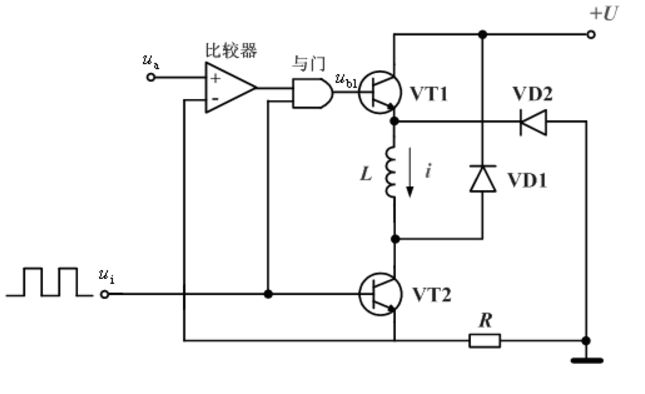
El circuit d'accionament de corrent constant de chopper és un tipus de mode d'accionament amb millor rendiment i més ús actualment. La idea bàsica és que el corrent nominal del debanament de fase conductora es manté independentment de si...motor pas a pasestà en un estat bloquejat o funcionant en baixa o alta freqüència. La figura següent és el diagrama esquemàtic del circuit d'accionament de corrent constant del chopper, en què només es mostra un circuit d'accionament de fase i les altres fases són iguals. L'encesa i l'apagada del debanat de fase es controlen conjuntament mitjançant els tubs de commutació VT1 i VT2. L'emissor de VT2 està connectat amb una resistència de mostreig R, i la caiguda de pressió a la resistència és proporcional al corrent I del debanat de fase.
Quan el pols de control UI és a alt voltatge, els tubs de commutació VT1 i VT2 s'encenen i la font d'alimentació de CC alimenta el bobinatge. A causa de la influència de la inductància del bobinatge, la tensió a la resistència de mostreig R augmenta gradualment. Quan se supera el valor de la tensió donada Ua, el comparador emet un nivell baix, de manera que la porta també emet un nivell baix. VT1 es talla i la font d'alimentació de CC es talla. Quan la tensió a la resistència de mostreig R és inferior a la tensió donada Ua, el comparador emet un nivell alt i la porta també emet un nivell alt, VT1 es torna a encendre i la font d'alimentació de CC torna a començar a subministrar energia al bobinatge. Una i altra vegada, el corrent al bobinatge de fase s'estabilitza a un valor determinat per la tensió donada Ua.
Quan s'utilitza un variador de tensió constant, la tensió d'alimentació coincideix amb la tensió nominal del motor i es manté constant. Els variadors de tensió constant són més senzills i econòmics que els variadors de corrent constant, que regulen la tensió d'alimentació per garantir que es proporcioni un corrent constant fix al motor. Per a un variador de tensió constant, la resistència del circuit de variació limitarà el corrent màxim i la inductància del motor limitarà la velocitat a la qual augmenta el corrent. A baixes velocitats, la resistència és el factor limitant per a la generació de corrent (i parell). El motor té un bon control de parell i posicionament i funciona sense problemes. Tanmateix, a mesura que augmenta la velocitat del motor, la inductància i el temps de pujada del corrent comencen a impedir que el corrent arribi al seu valor objectiu. A més, a mesura que augmenta la velocitat del motor, la força electromotriu posterior també augmenta, la qual cosa significa que només s'utilitza més tensió d'alimentació per superar la tensió de força electromotriu posterior. Per tant, el principal desavantatge del variador de tensió constant és la ràpida caiguda del parell produït a una velocitat relativament baixa del motor pas a pas.
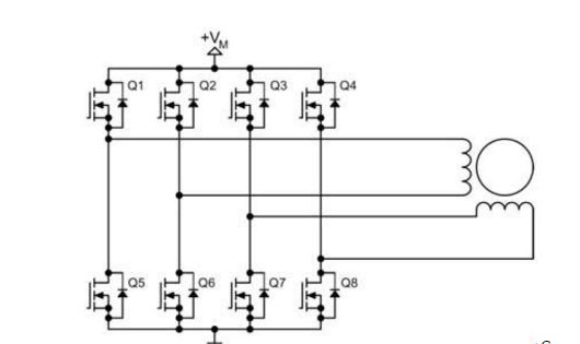
El circuit de control d'un motor pas a pas bipolar es mostra a la Figura 2. Utilitza vuit transistors per controlar dos conjunts de fases. El circuit de control bipolar pot controlar motors pas a pas de quatre o sis fils alhora. Tot i que el motor de quatre fils només pot utilitzar el circuit de control bipolar, pot reduir considerablement el cost de les aplicacions de producció en massa. El nombre de transistors en un circuit de control de motor pas a pas bipolar és el doble que el d'un circuit de control unipolar. Els quatre transistors inferiors solen ser controlats directament per un microcontrolador, i el transistor superior requereix un circuit de control superior de cost més elevat. El transistor del circuit de control bipolar només necessita suportar la tensió del motor, de manera que no necessita un circuit de subjecció com el circuit de control unipolar.
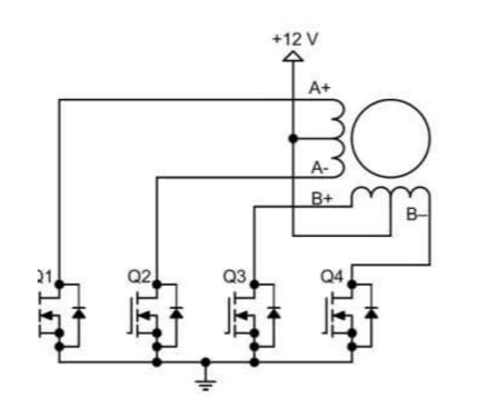
Els circuits d'accionament més utilitzats són els unipolars i els bipolars, que són els motors pas a pas. El circuit d'accionament unipolar utilitza quatre transistors per accionar els dos conjunts de fases del motor pas a pas, i l'estructura de l'enrotllament de l'estator del motor inclou dos conjunts de bobines amb preses intermèdies (la presa intermèdia de la bobina de CA O, la bobina BD és la presa intermèdia m), i tot el motor té un total de sis línies amb una connexió externa. El costat de CA no es pot energitzar (extrem BD), ja que en cas contrari el flux magnètic generat per les dues bobines del pol magnètic es cancel·la entre si, només es genera el consum de coure de la bobina. Com que en realitat només hi ha dues fases (els enrotllaments de CA són una fase, l'enrotllament BD és una fase), l'afirmació precisa hauria de ser de dues fases de sis fils (és clar, ara hi ha cinc línies, connectades a les dues línies públiques). Motor pas a pas.
Monofàsic, el bobinatge d'encesa només una fase, canviant seqüencialment el corrent de fase generant l'angle de pas de rotació (diferents màquines elèctriques, 18 graus 15 7,5 5, motor mixt 1,8 graus i 0,9 graus, els següents 1,8 graus es refereixen a aquest mètode d'excitació, i la resposta de l'angle de rotació quan arriba cada pols vibra. Si la freqüència és massa alta, és fàcil generar un fora de data.
Excitació bifàsica: corrent de circulació simultània bifàsica, també utilitza un mètode de commutació de corrents de fase al seu torn, l'angle de pas d'intensitat de la segona fase és d'1,8 graus, el corrent total de les dues seccions és 2 vegades, i la freqüència d'inici més alta augmenta, es pot obtenir una alta velocitat, un rendiment addicional i excessiu.
Excitació 1-2: Aquest és un mètode que consisteix a realitzar alternativament una excitació de fase, una excitació de dues fases i un corrent d'arrencada, cada dos sempre canvien, de manera que l'angle de pas és de 0,9 graus, el corrent d'excitació és gran i el sobrerendiment és bo. La freqüència d'arrencada màxima també és alta. Conegut comunament com a accionament d'excitació a mig camí.
Data de publicació: 06-07-2023


